Introduction
Quite often, it is desirable to deploy applications across datacenters. Those applications might be ok with a routed connectivity model, but there are also situations where a layer-2 connection model is desired. As an example:
- Clustered applications such as database or firewall clusters rely on a shared virtual IP.
- Mobility of VMs is desired across DCs. Preservation of IP address and network context is required here. In the case of VMware estate, this is implemented through VMotion within a (Metro-)cluster, or even across clusters.
- Disaster-recovery strategies where it is desirable to restore the VM with the same IP in a different datacenter.
This blog explains a few ways how to interconnect your datacenters, and also elaborates on how to expose the application externally using a datacenter gateway (DCGW). The assumption is that each DC is built in a leaf-spine topology based on Nuage Networks VSG or 210WBX, with eBGP sessions running between leaf/spine.
A follow-up blog will then cover more specifically on how to dynamically configure a stretched service on Nokia SROS.
DC Interconnection via VXLAN
To enable a stretched layer-2 overlay service, the “IP fabric” of “underlay network” can simply be extended across 2 or more datacenters. The most optimal way how to achieve connectivity between datacenters may differ on the size and fiber availability, and shall be described in further part of chapter. We distinguish basically between two cases, closely located DCs and remote DCs.
Closely located DC
The most common example of this use case are Twin DCs. Twin DCs are defined as two datacenters that have been built close to each other, with the idea of providing geo-resilience while exposing them as 1 logical entity to the application owners. The most cost effective way to interconnect such closely-located (large) Data Centers is to interconnect the Spine Layer via available fiber or DWDM transport. In that case the IP underlay is simply extended between two or more sites. An example is given in the following picture, in which the underlay network is designed using eBGP.
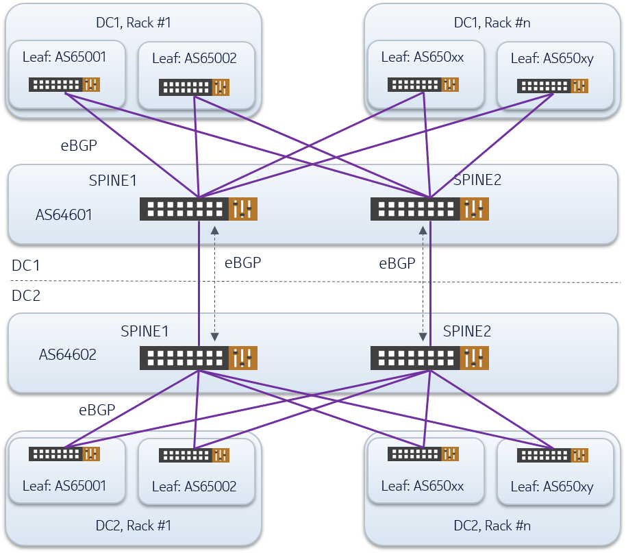
Note: the AS numbers given in the above pictures are pure examples, whereby an overlapping scheme is adopted as per RFC 7938
eBGP sessions are setup point-to-point between spine and leaf layer in each DC and between the spines layers. It is used to advertise the following information:
- System loopbacks
- Multichassis VTEP
- External networks connected to the fabric underlay
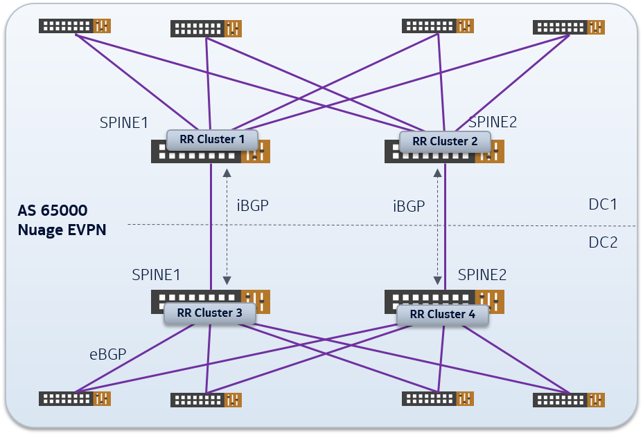
From an overlay perspective, any EVPN domain is simply extended across both DCs with routes exchanged over iBGP sessions, and configuring the spines as route-reflector.
Extension to Remote or Small DCs
For remote datacenters the option of dedicated fiber connectivity or DWDM channel may not exist or is too costly. Therefore we would recommend to interconnect such remote DC by the use of a so-called “infrastructure” VPN on a IP-VPN backbone, which will provide separated underlay transport over a potential global network. A schematic picture is shown below.
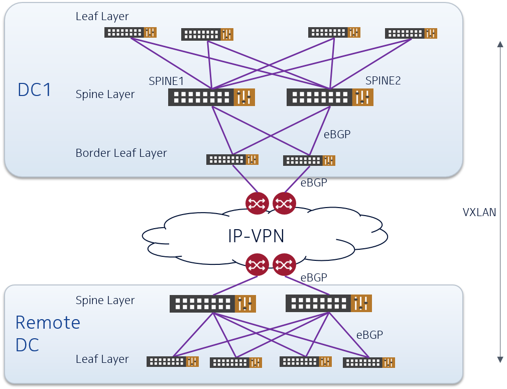
In this case the IP-fabric of the DCs gets extended across the IP-VPN backbone in a dedicated transport VPN. Connectivity from the DC towards the backbone can
- be realized by the use of the Border-Leaf switch as shown in the example in the main DC, or
- be directly from the Spine switch as shown in the remote DC.
Whether to connect from border-leaf or from spine depends on the expected north-south traffic and horizontal scale-out desired. So some capacity planning is required here.
In both cases some ports of Border-Leaf/Spine will be connected towards the CE router as pure IP/router ports (no VTEPs), thus extending the underlay IP connectivity.
Deployment of Nuage VSD in distributed DC environment
When it comes to distributed DC environments, one could deploy a global VSD instance or a VSD instance per site. In both cases, a stretched overlay network is established through a BGP federation between VSCs and/or route-reflectors.
Service handoff to a DC Gateway Router
This section shall explain how to hand off traffic from an overlay service to an external network. Basically the interaction (or peering) can be realized by a gateway router that is integrated from a BGP-EVPN/VXLAN perspective, or it can be an independent (3rd party) router.
Breakout from Nuage fabric to 3rd party Gateway Router
Assuming the Gateway Router will not be able to handle VXLAN-encapsulated traffic, we need a VTEP to terminate/initiate VXLAN tunnels that can be controlled by Nuage VSD. The natural instance is the Border Leaf Switch which can provide a plain Ethernet/VLAN/IP interface towards the Gateway Router per datacenter service.
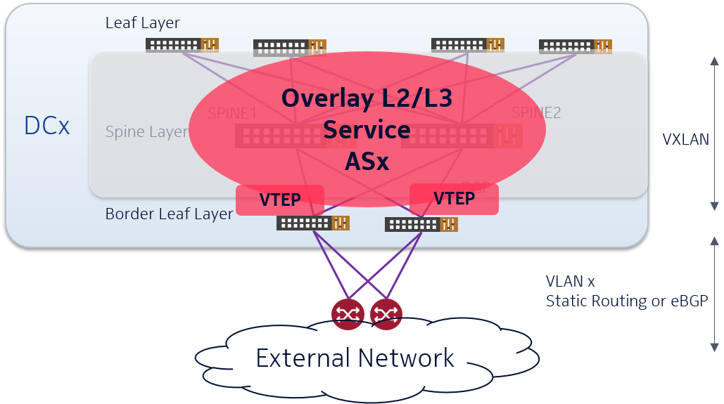
The border leaf switches are connected to the two routers that stitch the DC on the core network. Multiple physical or logical (VLAN) interfaces may be used to hand over different VPNs in the DC towards the backbone. Those VPNs could be L3 or L2 VPNs.
L3 Service breakout
For each Layer-3 Service the VTEP(s) on the Border-Leafs can be configured with a Inter-AS option A interworking towards the router. This means for each service a logical interface needs to be configured on both sides. Also routing has to be setup between the two entities: either via a BGP PE-CE configuration or via static-routing.
If the same L3 VPN is connected to the routers in multiple DCs, optimal routing from the outside back into the DC can be achieved by advertizing host routes from the gateway routers into the backbone. This is not always possible or desirable as the total number of endpoints could be rather high. As such, subnet-based advertizement could be considered. Suppression of host-routes could be configured dynamically out of Nuage VSD or manually on the gateway routers. The implication is obviously that inter-DC routing would happen in the overlay (VXLAN) domain, using the interconnectivity as described in previous section.
L2 Service breakout
For each Layer-2 Service the VTEPs on the border leaf will provide a VLAN towards the Gateway Routers. No special communication protocol to advertise MAC-addresses is needed. MAC learning will be based on flood & learn just like in any Layer-2 network.
To ensure all links are used between border leafs and gateway routers, two Border-Leaf switches can be paired in an Multi-Chassis setup running a link-aggregated-group (LAG) combining links of both switches. LACP then can be configured as control plane protocol. Alternative mechanisms protocols could be considered, depending on support of the 3rd party gateway (eg BGP Multi-homing or EVPN multi-homing). Most important is to have mechnisms in place to prevent (or block) loops.
If the Gateway does not support forwarding across multiple systems and/or across multiple links, only a single border leaf might be forwarding in the worst case across a multi-DC environment.
Using Nokia Service Router as Datacenter Gateway
Using the Nokia Service Router as DC Gateway allows for the direct termination of VXLAN on the router, and to run BGP-EVPN to the Nuage VSC. It has as advantage:
- Single interface provisioning between border leaf and DCGW to carry the VXLAN and BGP traffic
- Single BGP session to configure, to control and to monitor, instead of running a session per service
- Sub-optimal traffic patterns due to loop prevention or unknown prefix location can quite easily be solved:
- All links between fabric and Nokia SR can be used, since the fabric-to-dcgw are configured as ECMP links
- (incoming) Since Nokia SR learns the next-hop of each overlay end point, it can advertize host-routes or MAC addresses into the backbone network.
- (outgoing) By using BGP selection criteria, preference can be signaled to Nuae VSC on what the outgoing gateway router should be. If no specific configuration is done, then ECMP will be used between VRS adn DCGW.
Furthermore, Nokia has implemented mechanisms so that all DC Gateways - even when geographically dispersed, can actively forward packets back into the DC in both L2 and L3 cases. This is very different from a traditional STP or L2/L3 mechanism where only a single device is active forwarder.
Managing the Nokia Service Router out of VSD
When using Nokia SR as datacenter gateway, provisioning can be further simplified by putting the SR under the management authority of the VSD.
The complete service context for any new L2VPN or L3VPN in the DC can be automatically configured on the Nokia Service Router, including all interfaces which are needed from the Gateway to the outside world. This can happen as soon as a L2 or L3 domain is created in the VSD.
Other DC Interconnection mechanisms
While EVPN/VXLAN is probably the easiest method to create a DC interconnection, some cloud providers prefer to model each DC independently, and even allow overlapping IP address space between datacenters.
In those environments, a BGP federation cannot be established across sites, and each VXLAN needs effective termination at the datacenter gateway. Within the backbone/core, BGP-EVPN using MPLS or VXLAN can be used, or even plain routing in multiple VRFs. There are a number of techniques and best practices to follow in this model, but this is outside the scope of this blog.
What’s next ?
This blog has covered how you can setup overlay networks that stretch multiple datacenters using the Nuage VSP solution. It primarily focused on using VXLAN as interconnection protocol, and how you do a service hand-off to a 3rd party or Nokia datacenter gateway.
In the next blog, we will demonstrate what configuration is required on a Nokia Service Router to have it interact with Nuage VSC. It will also cover how you can use dynamic service provisioning to automate such extension, tackling this both from a Nuage VSD UI perspective and by using Ansible playbooks.